Sir Saiful Yusri, Our FYP Supervisor

He is our lecturer for the subjects 'Communication Technology' when we were in second semester and now he is our FYP supervisor.

Amalina, my partner!

Me with my partner, Amalina. Check out her FYP blog : soundtriggerfyp.blogspot.com

Sound Trigger

Our project 'Sound Trigger' circuit, without casing

Finally! Industry Day

On the Industry Day, all FYP student projects assessed by two lecturers.. Most nervous day for us but Alhamdulillah everything went well. :)

Look how happy we are :D

We are currently assessed by one of our assessors.

Sound Trigger Prototype

We build a model of a certain area in the house to show the situation where the Sound Trigger can be used, and where is the suitable place to put the Sound Trigger. The types of environment scenario which we were study is in closed area such as in our home. We make three compartment of house which is kitchen, stairs and and front of house. 


The one minute will allows time for someone to negotiate the stairs or make their way along the corridor, or perhaps to find the switch of the usual lighting and turn it on. A lamp and buzzer that comes on whenever a noise is heard in the vicinity is also an intruder deterrent. 


Jalan Pasar, again..

After the troubleshooting process is complete, we found several components that we use was broken and damaged. We decided to go to Jalan Pasar again to buy a new set of components, so that we can make a new circuit. We also bought a black casing to put the circuit inside it. The casing cost is RM 5.50.


How The 'Sound Trigger' Works


The Sound Trigger circuit consist of six distinct stages which most of the stages are coupled to the following stages and most stages are coupled to the following stage through a capacitor.

STAGE 1 : Microphone
An electrets microphone is used in this stage, MIC1, which depends for its action on the changes in capacitance that occur between a fixed plate and a plate that is being vibrated by sound. This type of microphone has a permanent charge across the capacitor, produce by heating the dielectric during manufacture while maintaining a strong electrical field between the plates. After a while, the microphone will be cooled and the electric charge remains.
This microphone also includes f.e.t.amplifier and requires a current to power it. After the sound is detected, there will be a voltage signal generated across the microphone and the signal will passes across the capacitor, which will bring us to the second stage, Inverting Amplifier.

STAGE 2 : Inverting Amplifier
The amplifier has an f.e.t. inputs and it is used in inverting mode with its specified gain set by the ratio of resistors. In this stage, the trimmer potentiometer, VR1 will adjust the voltage at the non-inverting (+) input to make it equal to the steady inverting (-) input after the sound is absence. Then, the output voltage of the amplifier (pin 6) will passes across capacitor (C2) to the next stage.


STAGE 3 & 4 : Diode Pump and Trigger Switch


The diode pump will rectify the signal and to produce a cumulative effect. The diode pump is used to avoid the cancelling triggering when the voltage swings to negative. Only when positive pulse generates, it can switches on the MOSFET TR1 (trigger switch) via capacitor C4.
           
STAGE 5 & 6 : Timer, Lamp Switch and Buzzer

When the TR1 is switched on, the timer which is IC2 555 will automatically trigger. This is wired as a monostable multivibrator which then produces high output pulse from pin3. The length of the pulse from IC2 (timer) depends on the value of resistor in this stages, R6 and C6. The value of the resistor is already set for timer: 50second to 60 second, which the time for the lamp and buzzer will come on. The changes of the length of the pulse can be made by choosing an appropriate values for R6 or C6. 


Troubleshooting Part II

The original circuit is originally design using a Variable Resistor VR1, 47k value. The VR1 function is to varied the sensitivity of the circuit. Specifically, VR1 will adjust the voltage at the non-inverting (+) input to make it equal to the steady inverting (-) input after the sound is absence.

The lower value of VR1, the more sensitivity the circuit will be. Means that, even a little sound detected can trigger the circuit. So, we decided to make the circuit is less sensitive. Sir Saiful suggested to us to use the value of VR1 in the range of 60k to 70k. We head down to Jalan Pasar again to search for that particular value of VR1, but we didnt manage to find one. We bought a 100k instead. 

We changed the value of VR1 from 47k to 100k in the circuit. The result is as expected. Using a 100k VR1, the sensitivity become less. 


The 47k value of VR1

The circuit VR1 is change to 100k value, can be seen in the bottom of the circuit, far left.


The bright lights have been dimmed after the VR1 is varied.


Poster and Pamphlet for Industry Day

Industry Day is the day where all the projects of Final Year Project's student will be assessed by two lecturers. Industry day is  held on week 14, also known as Engineers Day. 


We also need to prepare a poster and a brochure for the FYP presentation. 

Our Pamphlet Outside view

The inside view of our pamphlet

The Poster


Last Task : Sound Trigger's Casing

Week 14, Monday.

Four days left before the Industry Day, we have complete installed the circuit after buy the new set components and the casing on previous week. Our last task is now only to drill the casing so that the circuit can be put in the casing. Amalina did the drilling, and I put the circuit in it. 

Sound Trigger casing after drill


This is how the circuit looks like in the casing

That is our last circuit/project prototype preparation. All we need to do now is to be ready to address our self and be prepared for the Industry Day.

Troubleshooting

Troubleshooting process is the most difficult part of the Sound Trigger making process. After consult with Sir Saiful, we suspect two  problem that has occur on the circuit; that is :-

  1. The circuit is soldered wrongly.
  2. Both of the ICs in the circuit is damage because the circuit received wrong power supply.
Sir Saiful insist us to check the Datasheet for both of the ICs, we found out that its not the reason why the circuit is not working. The power supply given has nothing to do with it. 

Our Troubleshooting process takes about two week since we are busy with quizzes and assignments. Since we found a dead end, not knowing what is the reason why our circuit is not functioning, we asked for help from a student which is known by its expertise in dealing with circuits, Afdhal Atiff. Check out his Youtube channel that contained all the project that he has made. http://www.youtube.com/user/afdhalatifftan92?feature=watch.

After discussed with him, we manage to find out the problem encountered.

The problem encountered :-
  1. The ICs is damaged because one of the pins break
  2. The circuit is soldered wrongly in the 'Trigger Switch' section

The problem found encountered at stage ‘ Trigger Switch’. The resistor R4 (10kOhm) shown in the figure 4. below are supposed to be hold from reaching ground (GND) before the circuit receive any sound. 

The yellow and red box indicates where the problem encountered on the circuit

It is discovered that the R4 is always at ground, that is why the circuit does not work how it supposed to be. The problem was because of the solder. Two adjacent joints TR1 ‘d’ and  ‘s’ solder are contacting with each other which results in short circuit and the circuit not functioning properly. That is why the circuit act like a normal light circuit.

Using solder pump to suck back the solder lid at the TR1 ‘d’ and ‘s’ to fix back the problem. After that, the circuit works as the way it must be. 

After all, Sir Saiful suspicion about the reason why the circuit is not functioning was right. Thanks to Afdhal, we managed detect the problems in detail.


Testing The Circuit

Last week, we have finish installed the Sound Trigger circuit on strip-board but we didn't have the chance to try the circuit yet because we don't have a 12V supply. So this week, we manage to get the power supply, so we test the circuit out.

The complete circuit that has been installed properly on strip-board


12V DC power supply

The almost complete Sound Trigger prototype.

After test the circuit, we find that it did not respond to any noise. Our circuit become like a normal lamp circuit, because when we switch on the power supply, the lights comes on without hearing sound and it will off after one minute. The lamp of our circuit should be only comes on whenever a noise is heard.

We decided to consult with Sir Saiful first before we start to do Troubleshooting.

Assemble Components on Strip-Board


After testing the circuit by assemble the complete circuit on breadboard, its time for us to assemble the circuit properly on strip-board. We manage to add-on some component in the circuit, which is a 9V Buzzer.

The Buzzer is function to act as a intruder deterrent. The Buzzer will turn on together along with the lamp after the circuit. A toggle switch is connected with the Buzzer to make it optionally used by the user. 

This circuit assembled can be seen in the figure below.


After finish assemble on the strip-board, we proceed to the soldering process.


Since we don't have a 12V DC power supply at this time, we didn't directly try the circuit yet until we bought the power supply.


Testing Components on Breadboard

So this week we assemble all the components on breadboard. It takes about 3 to 4 days to assemble properly on breadboard. We test the circuit first on breadboard before we properly install it on strip-board.

By referring to the schematic and strip-board component layout, we successfully installed all the components on breadboard.


The strip-board component layout and the schematic diagram for Sound Trigger ( Picture Taken from Magazine EPE0104 )


After done assembled, we tested the circuit by giving the circuit 12v DC supply. The circuit seem functioning very well. Next step is to build the circuit at the strip-board.

Sound Trigger components

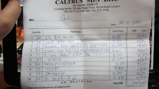
So this is all the components that we bought at Caltrus Sdn Bhd, Jalan Pasar. The total of all our components (3 set) is RM 52.80


The Resistor

The Capacitors

a 12V Lamp

Timer 555, TL071CP, Electret Mic and VN10KM Mosfet

A buzzer, 10kOhm Resistor and a toogle switch

E-Cap 47u and Diode 1N4148


 Now, since the component is complete, we just need to assemble all the components to start building the circuit.


Components Hunting at Jalan Pasar


Here is our list of components and material for making project : -

3 - RESISTOR 10KΩ (3 OFF) 
2 - RESISTOR 1MΩ (2 0FF)  
1 - RESISTOR 100kΩ               
1 - VARIABLE RESISTOR VR1 47K MINITURE CARBON PRESET, HORIZONTAL 
1 - CAPACITOR 22n POLYESTER FILM              
2 - CAPACITOR 10n POLYESTER FILM              
1 - CAPACITOR 1n POLYESTER FILM                
1 - CAPACITOR 47n POLYESTER FILM              
1 - CAPACITOR 100 POLYESTER FILM              
1 - CAPACITOR 47µ RADIAL ELECT, 35V         
2 - DIODE 1N4148 SILICON  
2 - TRANSISTOR VN10KM, MOSFET N-CHANNEL (2 OFF)       
1 - IC1 TL071CP, OP. AMPLIFIER, BI-F.E.T. INPUTS    
1 - IC2 555 TIMER    
1 - ELECTRET MICROPHONE INSERT                
1 - 12V 340Ma FILAMENT LAMP      

1 - Strip board
1 - 1mm terminal pins (5 off)             
2 - 8 pin d.i.l. i.c. socket (2 off)          
1 - Lamp socket (MBC or to lift LP1) 
1 - 9V Buzzer              
1 - Connector for D.C. supply unit   

My partner and I went down to Jalan Pasar, the famous place where several of electrics and electronics shop located. Most of BMI student buy their components here.
We go to one particular shop that my friend had suggested, Caltrus Sdn. Bhd.


As you can see in the pictures above, we manage to buy all the components for making our project. We bought three set of full-components for backup in case short-circuit happens or components ruined..

Project Planning

(Click to enlarge the picture)

This is our project planning. Project planning will help us to do work systematically and finish the task in designated period. Late Sir Azman has helped us in making this project planing last year. 


Sir Azman (aslo known as Sir MANG) or his full name, Nor Azman Bin Abdul Ghani is our former Engineering Design lecturer on semester 4.

On Engineering Design class, he taught us about the difference between Engineering Design and Final Year Project. Basically, engineering design is not much difference as the final year project, it is actually a preparation for all students currently taking final year project for semester 5. 

Below are some of the things we have done while taking ED subjects : -
  1. Project Presentation
  2. Logbook (Consist of 14 projects)
  3. Report Proposal
  4. PCB Etching

Sadly, He passed away on July 7th, 2012.
 

Segala jasa dan ilmu dari mu amat kami hargai, semoga arwah Sir Azman tergolong dalam golongan orang-orang yang beriman. Al-Fatihah. :)


Sound Trigger by Owen Bishop


From my last post, I mention about the confirmation of our FYP project. Our project is called ‘Sound Trigger’ by Owen Bishop. So for this post, I will explain the abstract of our project.

ABSTRACT


‘Sound Trigger’ is basically a circuit model of a sound-operated trigger that can be triggered by a sudden sound such as hand clap ordinary conversation or passing traffic. When the circuit is triggered by a sudden sound, the lamp that connected with the circuit will comes on and stays on for about  50 seconds.


Sometimes we wake up the middle of the night, just want to go to the toilet or go to kitchen to drink. In this situation where we are not aware and unconscious in the dark, we might bump into door or closet which we might will injured ourselves. Our project will help consumer in this very particular situation.


^^

Finding Partner, Supervisor and Project Title


First week of S1/2012, we have to choose our partner, supervisor and find our project for diploma fyp student, we can choose either we want to do in a group of two or doing the fyp solo. So we both agree to be partners for our fyp because we are in the same course and we have been working together in group work and labs since first semester ^^

This is us through out the year :P

After agreeing on being partner, we have to find the right project and supervisor. We can't choose any project that has been done recently. We discussedand we list down our former lecturers name that we think that can be our FYP supervisor. So we met sir Saiful Yusri, one of lecturer in telecommunication department and he also taught us Communication Technology subject in our second semester. We ask him to be our supervisor and he agreed. He also agree with our choice of project which is Sound Trigger by Owen Bishop

Therefore, we have managed to have our supervisor for FYP and also choose a very ideal project for us. Since then, our Final Year Project's journey began.

FYP Official Blog


Bismillahirrahmanirrahim. Assalamu'alaikum. ^^

We are, Amalina and Zahidah, S2/12 FYP student taking Diploma of Engineering Technology in Telecommunication. This is our Final Year Project blog, but this blog is run by Zahidah. For Amalina, her blog is http://soundtriggerfyp.blogspot.com/ . We will update every detail of our Final Year Project’s process from S2/12 week 1 until our project is done. Since we can choose either to update our FYP’s via blog or logbook, we choose to do blog instead of logbook because it’s easier to correct errors in terms of spelling, explain things through pictures, videos or links that can be given directly from any FYP related websites.

To our beloved FYP supervisor, Sir Saiful, hope you can give us the guidance that we need.

Please pray for us too InshaAllah :D