Sir Saiful Yusri, Our FYP Supervisor

He is our lecturer for the subjects 'Communication Technology' when we were in second semester and now he is our FYP supervisor.

Sound Trigger Prototype

We build a model of a certain area in the house to show the situation where the Sound Trigger can be used, and where is the suitable place to put the Sound Trigger. The types of environment scenario which we were study is in closed area such as in our home. We make three compartment of house which is kitchen, stairs and and front of house.  The one minute will allows time for someone to negotiate the stairs or make their way along the corridor, or perhaps to find the switch of the usual lighting and turn it on. A lamp and buzzer that comes on whenever a noise is heard in the vicinity is also an intruder deterrent.&n...

Jalan Pasar, again..

After the troubleshooting process is complete, we found several components that we use was broken and damaged. We decided to go to Jalan Pasar again to buy a new set of components, so that we can make a new circuit. We also bought a black casing to put the circuit inside it. The casing cost is RM 5.50. ...

How The 'Sound Trigger' Works

The 
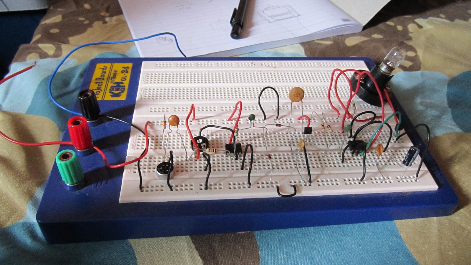
Sound Trigger circuit consist of six distinct stages which most of the stages are coupled to the following stages and most stages are coupled to the following stage through a capacitor. STAGE 1 : Microphone An electrets microphone is used in this stage, MIC1, which depends for its action on the changes in capacitance that occur between a fixed plate and a plate that is being vibrated by sound. This type of microphone has a permanent charge across the capacitor, produce by heating the dielectric during manufacture while maintaining a strong electrical field between the plates. After a while, the microphone will be cooled and...

Troubleshooting Part II

The original circuit is originally design using a Variable Resistor VR1, 47k value. The VR1 function is to varied the sensitivity of the circuit. Specifically, VR1 will adjust the voltage at the non-inverting (+) input to make it equal to the steady inverting (-) input after the sound is absence. The lower value of VR1, the more sensitivity the circuit will be. Means that, even a little sound detected can trigger the circuit. So, we decided to make the circuit is less sensitive. Sir Saiful suggested to us to use the value of VR1 in the range of 60k to 70k. We head down to Jalan Pasar again to search for that particular value of...

Poster and Pamphlet for Industry Day

Industry Day is the day where all the projects of Final Year Project's student will be assessed by two lecturers. Industry day is  held on week 14, also known as Engineers Day.  We also need to prepare a poster and a brochure for the FYP presentation.  Our Pamphlet Outside view The inside view of our pamphlet The Poster ...

Last Task : Sound Trigger's Casing

Week 14, Monday. Four days left before the Industry Day, we have complete installed the circuit after buy the new set components and the casing on previous week. Our last task is now only to drill the casing so that the circuit can be put in the casing. Amalina did the drilling, and I put the circuit in it.  Sound Trigger casing after drill This is how the circuit looks like in the casing That is our last circuit/project prototype preparation. All we need to do now is to be ready to address our self and be prepared for the Industry Da...

Troubleshooting

Troubleshooting process is the most difficult part of the Sound Trigger making process. After consult with Sir Saiful, we suspect two  problem that has occur on the circuit; that is :- The circuit is soldered wrongly. Both of the ICs in the circuit is damage because the circuit received wrong power supply. Sir Saiful insist us to check the Datasheet for both of the ICs, we found out that its not the reason why the circuit is not working. The power supply given has nothing to do with it.  Our Troubleshooting process takes about two week since we are busy with quizzes and assignments. Since we found a dead end, not knowing...

Testing The Circuit

Last week, we have finish installed the Sound Trigger circuit on strip-board but we didn't have the chance to try the circuit yet because we don't have a 12V supply. So this week, we manage to get the power supply, so we test the circuit out. The complete circuit that has been installed properly on strip-board 12V DC power supply The almost complete Sound Trigger prototype. After test the circuit, we find that it did not respond to any noise. Our circuit become like a normal lamp circuit, because when we switch on the power supply, the lights comes on without hearing sound and it will off after one minute. The lamp of our circuit...

Assemble Components on Strip-Board

After testing the circuit by assemble the complete circuit on breadboard, its time for us to assemble the circuit properly on strip-board. We manage to add-on some component in the circuit, which is a 9V Buzzer. The Buzzer is function to act as a intruder deterrent. The Buzzer will turn on together along with the lamp after the circuit. A toggle switch is connected with the Buzzer to make it optionally used by the user.  This circuit assembled can be seen in the figure below. After finish assemble on the strip-board, we proceed to the soldering process. Since we don't have a 12V DC power supply at this time, we...

Testing Components on Breadboard

So this week we assemble all the components on breadboard. It takes about 3 to 4 days to assemble properly on breadboard. We test the circuit first on breadboard before we properly install it on strip-board. By referring to the schematic and strip-board component layout, we successfully installed all the components on breadboard. The strip-board component layout and the schematic diagram for Sound Trigger ( Picture Taken from Magazine EPE0104 ) After done assembled, we tested the circuit by giving the circuit 12v DC supply. The circuit seem functioning very well. Next step is to build the circuit at the...

Sound Trigger components

So this is all the components that we bought at Caltrus Sdn Bhd, Jalan Pasar. The total of all our components (3 set) is RM 52.80 The Resistor The Capacitors a 12V Lamp Timer 555, TL071CP, Electret Mic and VN10KM Mosfet A buzzer, 10kOhm Resistor and a toogle switch E-Cap 47u and Diode 1N4148  Now, since the component is complete, we just need to assemble all the components to start building the circuit. ...

Page 1 of 41234Next